Dealing with the pull-up resistors on AVR
My internship project was to design a temperature monitoring system for the LSE server room. Several homemade temperature probes, based on NTC thermistors, are now arranged in the laboratory. Each of them is connected to a USB interface with a RJ-45 cable.
The interface is based on an Atmel AT90USBKEY, a development board based on
an AT90USB1287 microcontroller.
It features a 10-bit successive approximation Analog-to-Digital
Converter connected to an 8-channel Analog Multiplexer and a USB controller,
which allows us to create a proper USB HID device.
The host probes the interface to get the values of the different
temperature sensors and collects them thanks to
StatsD. The interface is exposed as a
character device if it’s binded to the appropriate driver and can communicate
with the user space via ioctl() syscall.
In our case, the interface is connected to a Sheevaplug, an ARM-based plug computer, which probes the values every 10 seconds and send them to the StatsD server via UDP.
The first problem I had to face is the strange values returned by the ADC on the channels 4 to 7 when no analog pin is connected:
$ cat /proc/temp_sensors
T0: 478
T1: 473
T2: 471
T3: 383
T4: 1019
T5: 1023
T6: 1023
T7: 1023
1023 is the maximum value of the ADC result, this means that the analog inputs were subject to a voltage equal to the reference voltage (here, Varef = 3.3V).
Thanks to AT90USB1287 documentation, we can see that pins PF4, PF5, PF6 and
PF7 are also used by the JTAG interface.
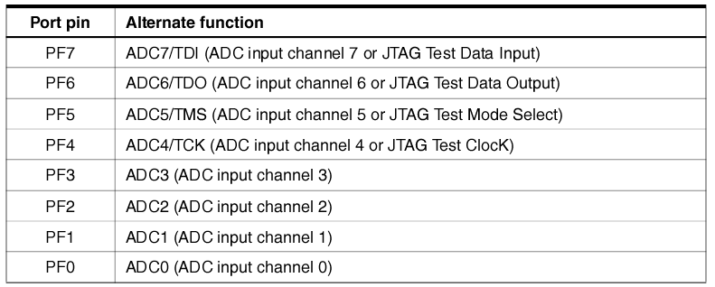
Port F pins alternate functions
If the JTAG interface is enabled, the pull-up resistors on pins PF7(TDI), PF5(TMS) and PF4(TCK) will be activated even if a Reset occurs. (AT90USB1287 specifications, Page 88)
In fact, it seems that the pin PF6 (TDO) pull-up resistor is also activated when the JTAG interface is enabled.
The input impedance of a converter is very high (due to internal operational amplifier), this justifies the fact that we find the voltage reference in the analog channels 4 to 7.
If we wanted to keep the JTAG enabled, the schematic of the electronic circuit would be:
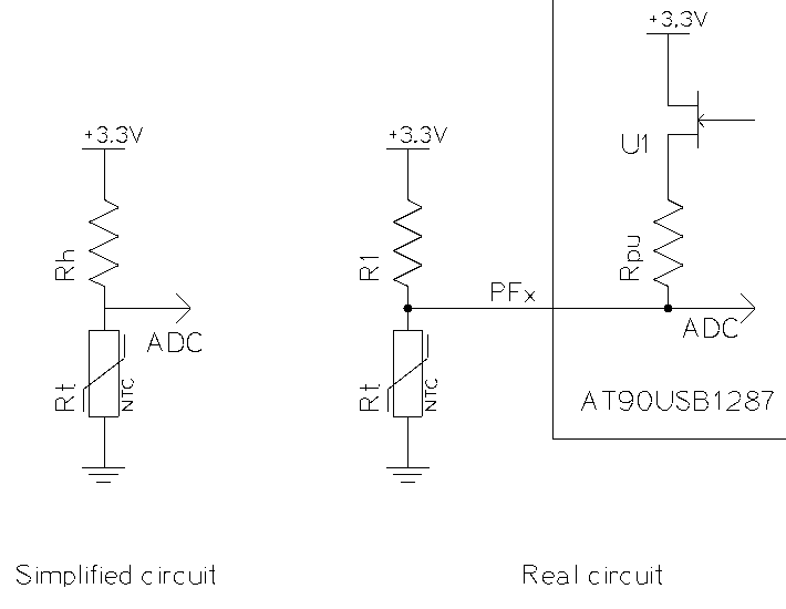
The equivalent resistor Rh can easily be calculated:
Then, the resistance of the thermistor, which represents the current temperature, is given by:
Theoretically, we could consider this pull-up resistor in the calculation of
the thermistor. However, the AT90USB1287 specifications indicate that the
values of the pull-up resistors are contained between 20KΩ and 50KΩ.
This interval is too large to properly calibrate the sensors.
Never mind: let’s disable the JTAG interface! We don’t really need it in our case.
The first way to do it is to unprogram JTAGEN fuse of the microcontroller. However, I can only use DFU (Device Firmware Upgrade) to program the device because I do not have the required equipment to use ICSP, JTAG or parallel programming for this kind of chip and, unfortunately, Fuses cannot be reprogrammed by the bootloader.
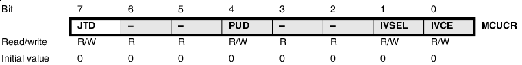
The other way is to set the bit JTD in the MCUCR register. In order to avoid unintentional disabling or enabling, the specifications ask to the application software to write this bit to the desired value twice within four cycles to change its value. This can be done with the following instructions:
asm volatile ("out %1, %0"      "\n\t"
              "out %1, %0"      "\n\t"
              :
              : "r" ((uint8_t) 1 << JTD),
                "i" (_SFR_IO_ADDR(MCUCR)));
Afterwards, the analog inputs 4 to 7 will get a normal behaviour and we can now use them to collect the different temperatures.
$ cat /proc/temp_sensors
T0: 478
T1: 383
T2: 348
T3: 376
T4: 310
T5: 278
T6: 257
T7: 107
All values returned by the device are proportional to the thermistors voltage. As Negative Temperature Coefficient thermistors, their resistance goes up as temperature goes down and the temperature/resistance curve is not linear. The temperature (°C) can be calculated from this resistance with the following expression:
- Rt = thermistor resistance (Ω)
- Rh = second bridge resistor (Ω)
- β = NTC parameter equation (here, β = 4092)
- T0 = 298 °K (273 °K + 25 °K)
- K0 = 273 °K (= 0 °C)
Finally, this temperature monitoring system seems to work and we are now able to see how temperatures of the laboratory evolves as a function of time.
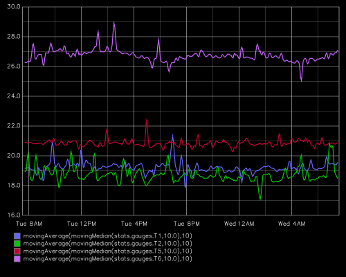
Evolution of temperatures (°C) as a function of time